Turnstile with Face Reader Installation
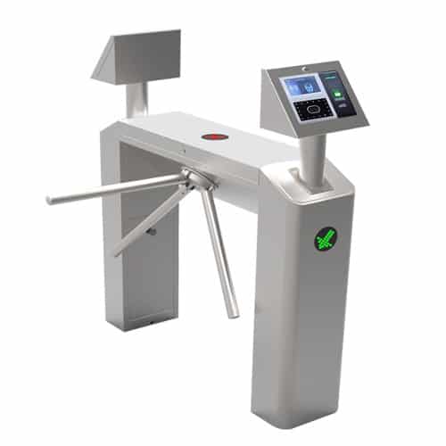
Turnstile with Face Reader
A turnstile, also called a baffle gate or turnstyle, is a form of gate which allows one person to pass at a time. It can also be made so as to enforce restricted traffic and authorized entry of people, and in addition, it can restrict access only to people who are identified after a bio-metric recognition process or RFID card recognition. Thus a turnstile can be used in the case of restricted access for employees to workplace, for example to gain access for authorized people alone to the office area.
Technical Specifications

Items In The Box
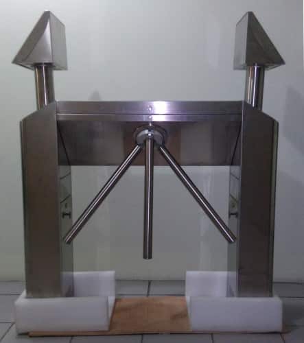
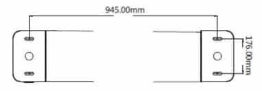
1. Turnstile Base
Side View
Front View
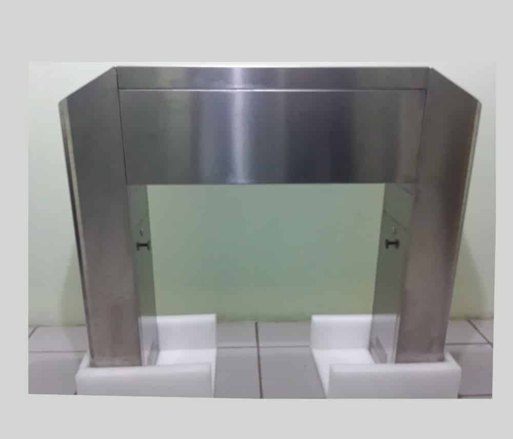
Rear View
2. Face Devices
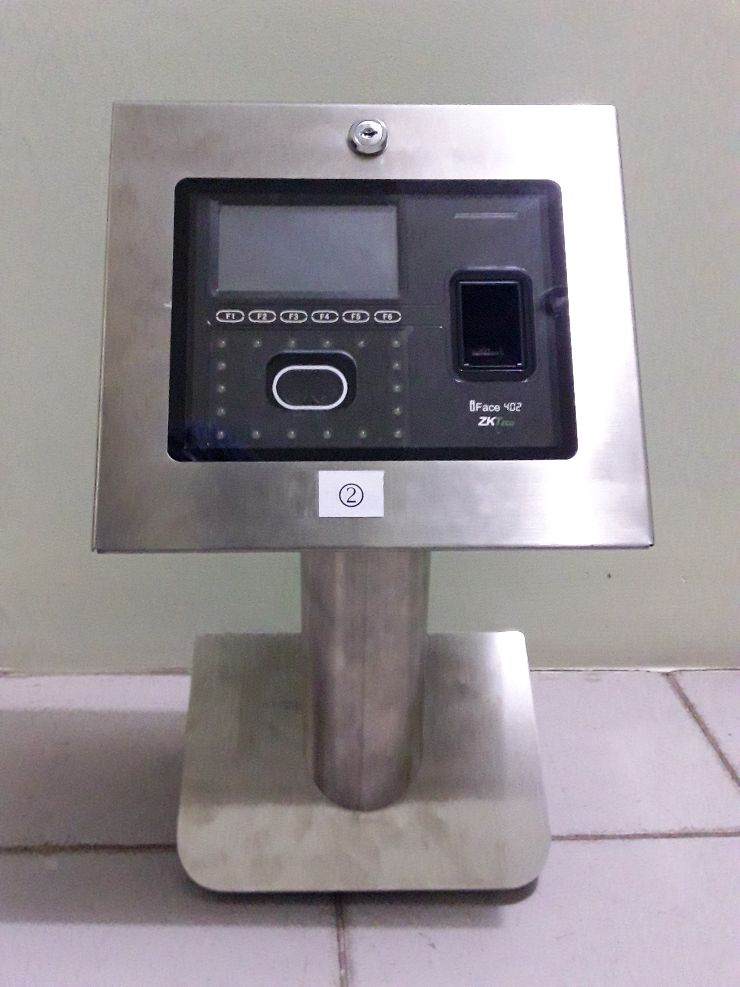
Face Device 1

Face Device 2
3. Turnstile Arms
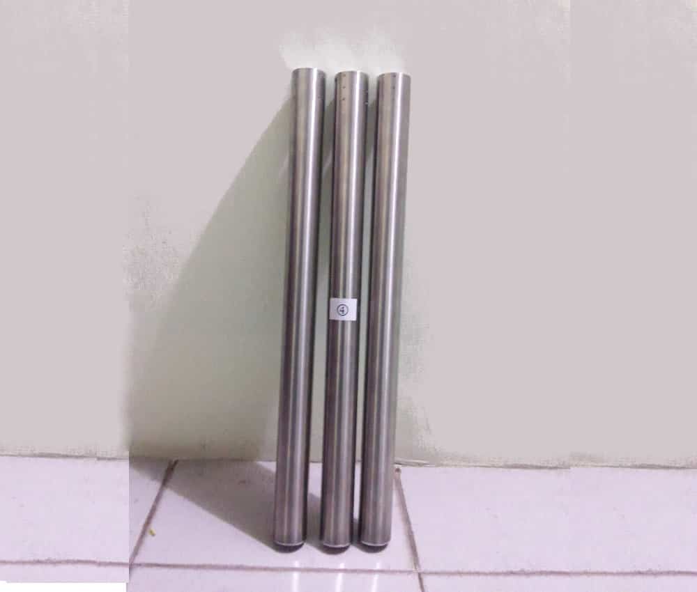
Arms
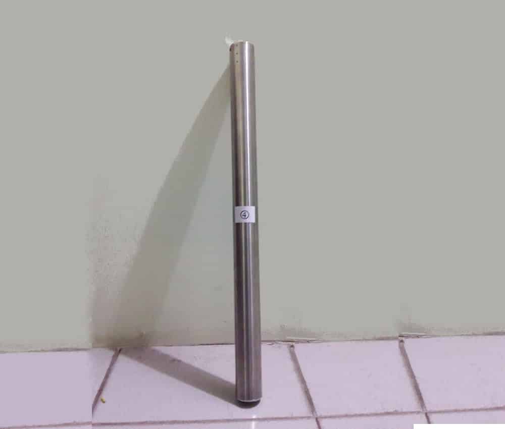
Single Arm
4. Other Items

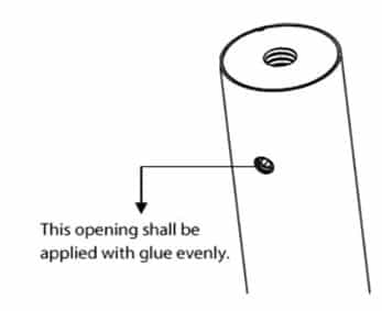
Glue

Align Key
Expansion Bolts
Steps for Installing Turnstile
Items in the box are to be assembled as instructed in the below steps
Connect Face Reader 1
The video below illustrates how to connect face reader to a turnstile.

Connect Face Reader 2
The video below illustrates how to connect face reader to a turnstile.
Connect Cables/Sockets
The video below illustrates the cable and socket connections to be made in the turnstile.


Connect LAN to Face Readers
The video below illustrates how to make the LAN connections to face reader.
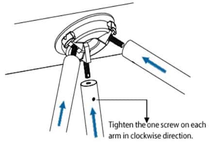
Install ARMs to Turnstile
The video illustrates how to connect the arms to the turnstile.
Equipment Installation
Installation Conditions
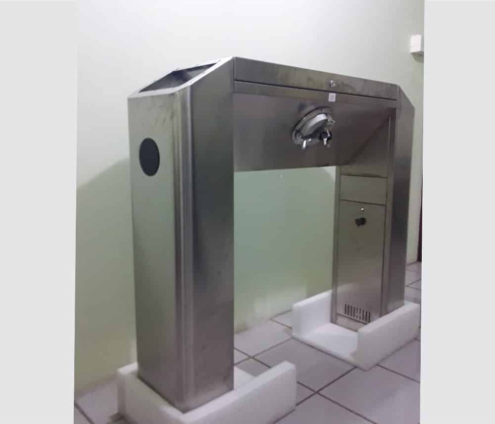
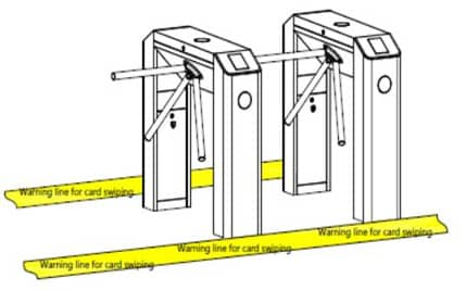
The equipment must be installed on concrete ground, ensuring that expansion bolts (refer items in the box above) can be secured firmly. You are suggested to install an assistant framework or fence to form a passageway, as shown in figure .

Cabling
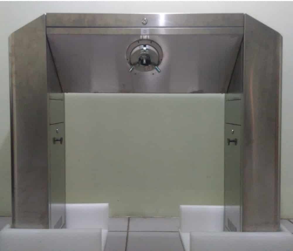
There are inlets in the bottom plate for cabling, as shown in figure. The turnstile requires a power input and LAN cables for each face reader. It is recommended to conceal the incoming cables under the floor. Cable protection covers are suggested to use if it is surface mounted.
Warning: The tripod turnstile must be connected to Ground (earth), there is wiring interface in the power switch.
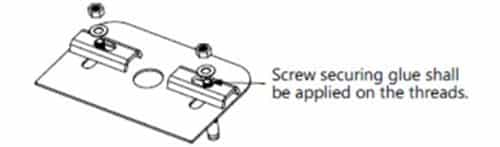
Installation