Bio-metric Access Control Master and Slave Device Connections

Access Control Bio-metric Device

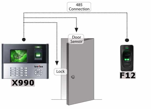
Access control bio-metric devices can perform authorisation, authentication, access approval etc of employees into work premises. The primary components for setting up bio-metric access control system consists of a Master Device (Entry Device), Slave Device (Exit Device) and Electromagnetic Lock. We explain here how to set up the master and slave devices for the configuration of access control system.

  • Superior access control by both detecting and deterring unauthorized entries
  • Turnstiles easily integrate with a building’s access control system
  • Turnstiles enhance facility operations by streamlining the entry process
How to Install Bio-metric Access Control Master and Slave Device

Instructions on how to connect the Master Device with Slave Device

Purchase Now

Items, master device and slave device, are to be connected as per the following instructions.

The item box delivered to you by Lenvica will contain the master and slave devices along with wires required for the connectivity. Please take note of the instructions below and proceed for a successful installation of master and slave device.
Purchase Now

Installation Conditions

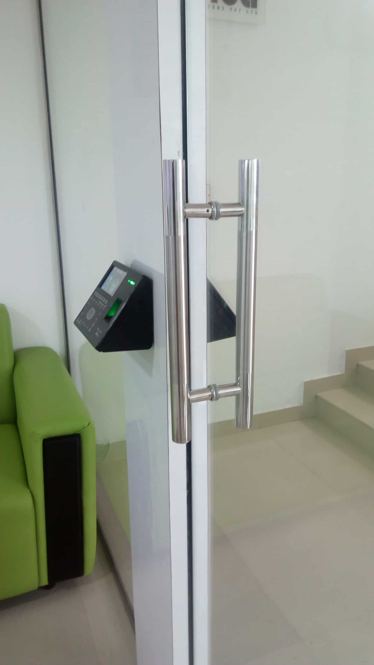
Screw in the master device on one side of the wall, near to the door and on the entry side where employees enter for work. The master device will be connected to the power supply and the slave device will be connected to the master device using wires supplied in the item box. The only connection to slave device will be this wire drawn from the master. The slave device can be screwed to the wall inside the office so the employees can register punch when they exit from office after work.A LAN cable has to be pulled to connect the master device to the network.

  • Screw both devices on either sides of the wall on which the door is fixed. Master device on the outside from where the employees will login for work and the slave device on the inside.
  • Master device has to be fed with Power supply and LAN connection. RS485 wire in the box can be used to establish the connection between the master and slave device. Note that the only connection to slave device will be the RS485 wire connection from the master through which the control and electric power to the device come.
  • Now to configure the devices to deliver IN and OUT punches separately as they log IN (Master device) and log OUT (Slave device), the anti pass back setting has to be active.
    Go to the Master Device menu -> Click on Access Control icon -> You can see two options inside access control menu
    Anti Pass Back
    Device Status

    Click on Device Status and make it as ‘IN’, save that and move to the other icon Anti Pass Back and set it as ‘Attendance State Saved’.
    Go to Access Control icon inside the master device menu
    Configure the Device Status = “IN’
    Set Anti Pass Back as ‘ Attendance State Saved’